


CAM software for the Pocket NC machine
How to use DeskProto with the Pocket NC V2 milling machine
The Pocket NC machine by Penta Machine Co is an intriguing machine It offers five-axis milling in a desktop machine, at a very reasonable price. As DeskProto offers support for rotation axis machining ánd for 5-axis machining, both at a low cost, the combination of a Pocket NC machine with the DeskProto CAM software offers a lot of value for little money.
For this combination you need to use the Multi-Axis edition of DeskProto.
Important is to use a recent version of DeskProto V7.1: the drivers for the Pocket NC V2 (machine definitions and postprocessor) are present since Revision 11098 (build date 2023-May-11).
And in order to use the TCPC workflow you need the Pocket NC control software (called the Kinetic Control user interface) released on 2021-Nov-1 (or newer).
On this page:
- 1. The Pocket NC V2 machine
- 2. Three-axis machining on a Pocket NC
- 3a. Rotary machining on a Pocket NC (using the Center of rotation as origin)
- 3b. Rotary machining on a Pocket NC (using TCPC)
- 4a. Indexed machining (five-axis) on a Pocket NC (using the Center of rotation as origin)
- 4b. Indexed machining (five-axis) on a Pocket NC (using TCPC)
- 5. Coordinate systems of the Pocket NC
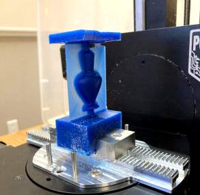
1. The Pocket NC V2 machine
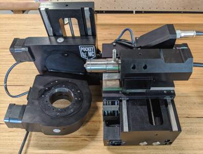
The left image shows the Pocket NC V2 machine, with the A-axis at ca 5 degrees.
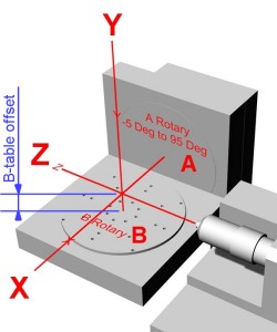
The drawing shows the orientation each of the five axes.
The drawing shows the orientation each of the five axes.
The Pocket NC is a very small machine ("Pocket"): the total width of what you see here is ca 45 cm. And the machine's total weight is only 13.6 kg.
The axes of this cute little machine are not aligned in a usual way: a Pocket NC has a horizontal Z-axis. On almost all other CNC milling machines the Z is vertical: the cutter then comes from above.
The B-axis (rotates round Y) is built on top of the A-axis (rotates round X), which is the standard scheme for 'trunnion-style' five-axis machines.
So with the A-axis rotated to 90 degrees the result is a standard 3-axis machine ("lying on it's side").
And with the A-axis rotated to 0 degrees (as shown in the schematic drawing) it can be used as a machine with a fourth axis, with the B-axis used as rotation axis (so using Y,Z,B coordinates for rotary toolpaths instead of the default X,Z,A).
Finally it can of course be used as 5-axis machine.
DeskProto V7 can easily be adapted to this machine configuration: in the machine definition (Advanced settings) you need to check both
- "Machine with 4th axis parallel to Y (swap X and Y coordinates in the NC file)" and
- "Use B command for this 4th axis (so also swap A and B)".
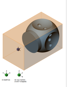
This has already been done in the Pocket NC V2 machine definitions that come with DeskProto. To remind you about this an extra orientator will be shown on the DeskProto screen.
So it is important to realize that in the NC file the X and Y axes are swapped: what you see as X on the DeskProto screen will be Y on the Pocket NC machine! This is clearly shown on the DeskProto screen: see the screenshots below.
Method A: use the Center of rotation as Origin
A great feature of the Pocket NC is that the machine's origin is automatically set - on the point where the two rotation axes intersect. This is the machine's Center of Rotation. This point can be set as origin by executing a G55 command and a G43 command at the start of the NC-file: the DeskProto postprocessor adds these commands automatically. In DeskProto it is easy to create NC toolpaths that use this center of rotation as workpiece zero point in the NC file, which will be explained below. This also is the method that is used in de DeskProto 5-axis tutorial video and in the PDF tutorial book.
Method B: use TCPC control
With a Pocket NC you have a second option: it offers an advanced feature called TCPC control. This Tool Center Point Control option allows you to select a different origin (different from the one used in the NC file).
To use TCPC the NC file needs to have its origin (the zero point of the CAM work center coordinates) at the center of the geometry. The position of the block (stock) on the machines does not need to be in the center. The user detects the position of the stock by making the cutter touch the block for all three axes and entering the three "touch off" values as "G5x work offsets" in Kinetic Control. The TCPC software then will convert the original toolpaths to paths relative to the new origin. How this works is explained in the Kinetic Control Software Overview by Penta Machine Co.
On this page three workflows are shown that use the machines Center of rotation (method A): three-axis, rotary and indexed. In addition two PDF tutorials are present (published by Penta Machine) with step-by-step instructions that show the workflow using TCPC (method B): rotary and indexed.
A next great feature of the Pocket NC is that an on-line simulator is available, allowing you to test your G-code before running it on the machine: sim.pentamachine.com.

2. Three-axis machining on a Pocket NC
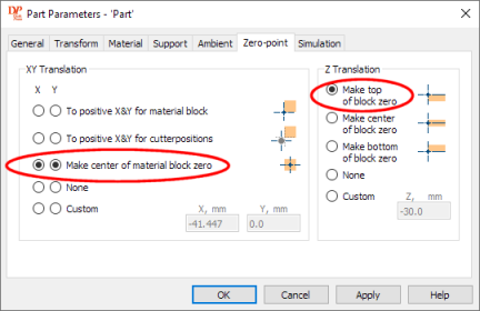
DeskProto translation settings to position X and Y zero in the center of the block, and Z zero at the top: perfect for a Pocket NC.
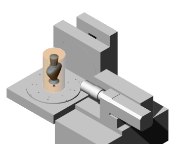
As mentioned above: with the A-axis rotated to 90 degrees a Pocket NC machine can be used as a standard 3-axis machine, see the illustration below. The easiest way to use it for three-axis machining is to clamp the material in the center of the machine's working table. In DeskProto it is easy to set the zero position in the center of the part: see the screenshot of the Zero point settings above. For Z you can select "Make top of block zero".
On the machine you then can use the default machine origin (the Center of Rotation) for X and Y, and touch the top of the block with the cutter to set Z=0. On the Pocket NC such "touch off" is possible only when the A-axis and the B-axis both are at 0 degrees. The touch-off then is done along the Y-axis (do not forget to compensate for the cutter radius). The Y touch off value automatically translates to a Z value when the A-axis is rotated to 90°.
The important detail is that you need to rotate the A-axis to 90 degrees before you start machining: see the illustration below. You can enter that rotation command as one of the Operation's Start/End commands (in order not to forget it...).

Left the DeskProto screen for three-axis machining half a perfume bottle.
Right the Pocket NC configured for 3-axis machining.
Note the workpiece zero point: left in blue, right (for better visibility) in red.
Note the workpiece zero point: left in blue, right (for better visibility) in red.
Here is the workflow for 3-axis jobs:
- In DeskProto select one of the Pocket NC V2 machines.
- In DeskProto set the X and Y translation on "Make center of part zero", and the Z-translation to "Make top of block zero". This results in the workpiece zero point shown in the illustrations above.
- Calculate toolpaths, write the .ngc file and copy it to the machine's control PC.
- Clamp the stock centered on the table.
- Rotate the A-axis to 0 degrees and the B-axis to 0 degrees.
- Open the .ngc file from DeskProto in the Kinetic Control interface.
- Jog the Y axis so the tool touches the stock and then home the Y axis (in the G55 Work Offsets of Kinetic control enter the cutter radius as new DRO value for Y).
- Rotate the A-axis to 90 degrees and the B-axis to 0 degrees to create a 3-axis machine.
- Start machining.
3a. Rotary machining on a Pocket NC
(using the Center of rotation as origin)
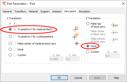
DeskProto translation settings to position X=0 at the left edge of the block and Z=0 with the tip of the cutter on the rotation axis.
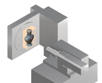
For rotary machining it is easiest to locate the WorkPiece zero point (that is how DeskProto calls the Origin) on the rotation axis. As the default machine origin of the Pocket NC (the Center of Rotation) is on the rotation axis we can simply use that as workpiece zero point. On the machine this is the point where the A-axis and B-axis intersect, and the machine 'knows' where this point is located. DeskProto will tell the machine to use that point as origin by writing a G55 command and a G43 command in the NC file.

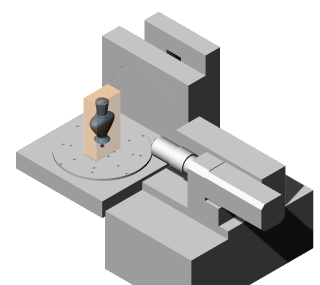
Left the DeskProto screen to rotary machine the perfume bottle.
Right the Pocket NC configured for rotary machining.
Note the position of the workpiece zero point: on the rotation axis, at the edge of the block.
The image above shows the machine prepared for rotary machining: the A-axis on 0 degrees, the B-axis can keep rotating. The block needs to be large enough, needs to be centered, and needs to be correctly positioned along the Y-axis: the Center of Rotation is located ca 0.839" (21.311 mm) above the B table. This distance is called the B table offset.
An important detail is that you need to rotate the A-axis to 0 degrees before you start machining. You can enter that rotation command as one of the Operation's Start/End commands (in order not to forget it...).
You can find much more information about how to create rotary toolpaths in DeskProto in the tutorial video about this subject.
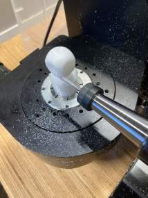
Rotary machining on the Pocket NC, with the stock centered on the working table.
Here is the workflow for rotary jobs:
- In DeskProto select one of the Pocket NC V2 machines.
- In DeskProto set the X-translation on "To positive X for material block", and the Z-translation on None.
- Calculate toolpaths, write the .ngc file and copy it to the machine's control PC.
- Clamp the block centered on the table.
- Rotate the A-axis to 0 degrees, which will make the B-axis vertical.
- Open the .ngc file from DeskProto in the Kinetic Control interface.
- Start machining.
3b. Rotary machining on a Pocket NC (using TCPC)
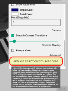
Left: in order to use TCPC the G-code needs to be converted.
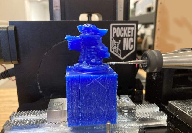
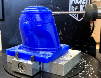
Right you see the PocketNC running the finishing operation of the Mandalorian helmet
Right you see the PocketNC running the finishing operation of the Mandalorian helmet
As mentioned above, TCPC means Tool Center Point Control. This advanced feature is offered by Penta, and involves:
- measuring the position of the stock (which needs not be centered)
- converting the G-code using the Penta simulator
- making some settings in the Kinetic Control interface.
For support on how to use TCPC you can best contact Penta support, as here at DeskProto we do not have any hands-on experience with that workflow.
4a. Indexed machining (five-axis) on a Pocket NC
(using the Center of rotation as origin)

DeskProto translation settings, specifying "None" for all three axes.
On this 5-axis machine DeskProto can also be used for indexed machining. This means to use several sets of 3-axis toolpaths, each from a different side of the part, with rotation commands in-between. As in DeskProto rotating the geometry is done in the Part parameters, for each side a new part will be added to the project. The rotation commands for the machine are entered in the operation's Start/End commands. The tutorial video on indexed machining explains in detail how this works.
For each next orientation DeskProto will define a new part, rotate the geometry and then calculate XYZ toolpaths. The important thing to keep in mind is that DeskProto performs these rotations (both A and B) round the zero point as defined in the CAD-data (the point where the main axes intersect). In order to let the machine rotate round that same zero point the translation settings in DeskProto need to be None for all three axes: then the CAD zero point will also be applied in the G-code, and the toolpaths for all sides will perfectly match.


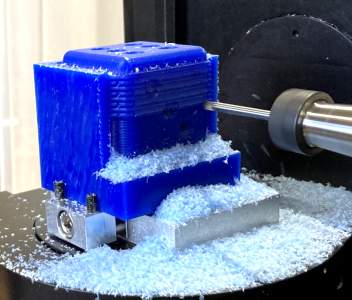
Indexed machining on a Pocket NC: left the DeskProto screen to calculate the toolpaths for the top, next how the part is orientated on the machine (A-axis at 90 degrees), and right machining the top.
On the machine you need to simply use the machine's Center of Rotation: the point where the A-axis and the B-axis intersect. DeskProto tells the machine to use that point as origin by writing a G55 command and a G43 command in the NC file. A great feature of the Pocket NC is that this origin is automatically set, and also that it is accurately set. The most common problem with indexed machining is that the origin is not accurately set, with the Pocket NC you do not need to worry about that. The toolpaths from all sides will be perfectly aligned.

Left: creating 3-axis toolpaths for the side with the two dots in DeskProto.
Next how this part is orientated on the machine, and right machining that side on the Pocket NC.
Next how this part is orientated on the machine, and right machining that side on the Pocket NC.
The illustrations show how to machine a die from five sides: the top is machined with the A-axis at 90 degrees and the B-axis at 0. The four sides are machined with the A-axis at 0 degrees and the B-axis at 0, 90, 180 and 270 degrees. The screenshots show the position of the origin (the small blue cube): as long as that is correctly set the toolpaths for all sides will automatically match. You can even mix with rotary toolpaths. The block needs to be mounted in the center of the rotary table.
Indexed machining from two sides. The bottle geometry is of one of the DeskProto sample files.
Indexed machining can also be used for more simple setups, for instance to machine a part from two sides, see the illustration above. Again the block needs to be mounted in the center of the rotary table.
Here as well the TCPC feature offers more flexibility for the position of the stock and of the zero point. For instance when you are using the 'Pocket NC Custom Vise' you need to use the TCPC method as that vise does not center the block. That workflow is described in the next paragraph.
4b. Indexed machining (five-axis) on a Pocket NC (using TCPC)
Left: in order to use TCPC the G-code needs to be converted.
Right you see the PocketNC running the finishing operation of side 3
Right you see the PocketNC running the finishing operation of side 3
As mentioned above, TCPC means Tool Center Point Control. This advanced feature is offered by Penta, and involves:
- measuring the position of the stock (which needs not be centered)
- converting the G-code using the Penta simulator
- making some settings in the Kinetic Control interface.
For support on how to use TCPC you can best contact Penta support, as here at DeskProto we do not have any hands-on experience with that workflow.
5. Coordinate systems of the Pocket NC
Most small CNC milling machines that we have worked with have two coordinate systems: the machine coordinates and the workpiece coordinates.Machine coordinates are present on a machine with limit switches. At startup it performs a reference run: on each axis it moves to a limit switch and sets the coordinate on 0.0 for that position. Do this for all axes to set the machine origin, the resulting coordinate system is called the machine coordinate system.
Workpiece coordinates are set when you start a job: you move the cutter to the desired origin, and press a button to set that as zero point for this job. The new coordinate system is called the workpiece coordinate system.

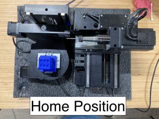
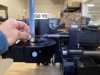
Left the Pocket NC machine origin, right its home position.
The Pocket NC offers this functionality too, however the process and the names are a bit different.
Machine coordinates are present too, and the Machine origin is located with X=0 and Y=0 at the machine's Center of Rotation (the point where the two rotation axes intersect), and Z=0 at the max Z.
This coordinate system is used when the movement command starts with G53. So the left photo above shows this position, which is reached after performing these commands:
G53 G0 X0
G53 G0 Y0
G53 G0 Z0
The photo on the right shows the machine's Home position, which is reached via these commands:
G53 G0 Z0.
G53 G0 X63.5 Y63.5 A0 B0
This is a safe place: any rotation command now can be executed without the cutter damaging the part. The DeskProto postprocessor writes these two lines at the start of each NC file.

Left the Pocket NC with the cutter at its Center of Rotation,
right the height of this point above the B-table (ca 0.839").
right the height of this point above the B-table (ca 0.839").
For the rest of the NC file DeskProto writes a line G55, which calls the G55 coordinate system. By default for X and Y this is the same as the G53 system just shown, however for Z it applies the Tool length compensation offset, which is activated by running a G43 command. The photo left shows the result: at Z=0 the tip of the cutter now is located exactly at the machine's Center of Rotation. The Center of Rotation is located ca 0.839" (21.311 mm) above the B table (this distance is called the B table offset).
This G55 origin can be changed by performing "touch offs": touch the block with the cutter and enter the resulting coordinate value as G55 work offset in Kinetic Control. Such touch offs can be done only when the A-axis and the B-axis both are at 0 degrees.