




How to CNC machine a Christmas decoration
CNC machine a decoration to be hung in the Xmas tree.

Machining the decoration in wood, to be hung in the tree as "Christmas bauble'.
When it is almost Christmas I want to use my CNC milling machine to create a Christmas decoration. I found a nice STL file that I could use: the image above shows the small wooden sculpture being machined (to be hung in our tree).
Below I will explain what I did, step by step, and show the result. A very nice detail is that the toolpaths for this nice decoration can be created using the Free edition of DeskProto, that can be used free of charge.
- 1. Find your CAD data
- 2. Load your CAD file in DeskProto
- 3. Check machine and cutter definitions
- 4. Calculate the toolpaths that you need
- 5. Send the toolpaths to your CNC machine
- 6. Admire the result.
1. Find your CAD data

A nice bas-relief, in the CNC3DMODELSStore on Etsy.
I started the project by searching the Internet for a nice design. Many CAD-files are available for download, both 2D vector files (SVG) and 3D geometries (STL). In the 'Links' section of this website you can find a list of websites that offer such downloads, or you can of course simply use a search engine. I found this nice bas-relief on Etsy.com (the download is called 3d-stl-model-for-cnc-router-engraver).
This design is a paid download: after ordering I could immediately download the STL file of this design. When paying is not an option: many free designs can be found as well.
2. Load your CAD file in DeskProto

The DeskProto screen after loading the STL file.
In DeskProto you start with opening a new Geometry project. Next you load your CAD file. It is an STL file (3D), so you need to use the option 'Load Geometry file' (or you can use the wizard 'Basic geometry machining'). When you start with an SVG file (2D) you need to use a Vector project and the option 'Load Vector file' (or use the wizard 'Basic vector machining').
DeskProto will immediately show the design, which you can view from all sides. The default material block is bounding box, the Part information dialog shows its dimensions. You can see that this geometry is correctly orientated to machine the relief: the cutter comes from the positive Z-direction.
3. Check machine and cutter definitions
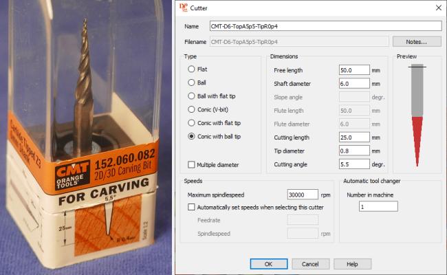
Left the tapered cutter to be used, right the cutter definition.
You can check which Machine is selected in the Project parameters (Parameters menu). That setting should be correct, as after installation DeskProto has asked you which machine you are using. If it is not correct you can select a different machine, from a very long list. If your machine is not present in DeskProtos Library of machines see page Which CNC machine to select in DeskProto.
The machine that is selected sets which postprocessor DeskProto will use, making sure that all NC files to be written are in a format that your machine will understand.
The Cutter that I wanted to use was not yet present in the list of cutters, so I needed to add it. That can be done in the Library of cutters (Options menu), using button Add. Left you see the cutter that I bought, made by CMT Orange Tools in Italy. This is called a tapered cutter with a ballnose tip. This type of cutter is a great tool for projects like this, as it can both remove much material and create small details. At the right side you see the DeskProto dialog to define this cutter. Note the difference between top angle (included angle) and side angle (grinding angle), as both values are used in cutter definitions. DeskProto uses the side angle.
4. Calculate the toolpaths that you need

The calculated toolpaths: left in the Free edition, right in the Multi-Axis edition.
The first thing that needed to be done was defining the correct size for this decoration. We just saw that the size was 322 x 450 x 12. In the screenshot these were mm - when you are using inches the same numbers will show as inches. In both cases too large for a tree decoration. In DeskProto the size can be set in the Part parameters, tab Transform. I switched form 'Scale factors' to 'Dimensions' and set the Y-dimension to 50 mm (ca 2 inches), to match the block of wood that I wanted to use. X and Z will automatically be scaled as well, as Uniform is checked. Next I unchecked Uniform and doubled the size for Z, to make the relief more clear.
On tab Material of the same Part parameters I also changed the Block size, by roughly doubling the minimum Z (from -2.8 to -6). Otherwise the part would be too thin and would easily break. When you use the wizard make this change using button 'Detail settings', as you want to change only the minimum Z.
The last few settings can be done in the Operation parameters. On tab page General you can select the Cutter to be used, I selected the cutter definition that I just created.
The other important setting in this dialog is the Precision: both the Distance between the toolpaths (also called Stepover) and the Stepsize along toolpath (as each path is build using steps: small straight line-segments). For an accurate result, with small details visible, I set both to 0.09 mm (0.0036 inch). The next step is to calculate the toolpaths (Create menu).
In the above screenshot on the left side you can see the resulting toolpaths for the Free edition. One operation, the complete block is machined, using parallel toolpaths at full depth (no roughing). For most wood types that will not be a problem.
At the right side the toolpaths are shown that were used in the video below, made with a paid license. Here you can see two operations: roughing and finishing; the finishing is limited to only the geometry, not the rest of the block.
As a final check before starting your machine you can now tell DeskProto to show a Simulation (Create menu).
5. Send the toolpaths to your CNC machine
This video shows the complete production process (DP V7.1, 2¼ min)
This short video shows all steps in the production process, including the bandsaw machine as final step. The toolpaths used are by the Multi-Axis edition: roughing with a 6 mm ballnose and finishing with the tapered cutter. Reason was that the maple wood that was used is quite hard, so I decided to be careful. For that same reason three roughing layers have been used. As the part is very small the total machining time was small anyway.
6. Admire the result.

The resulting decoration: a beautiful addition to the Christmas tree.
We hope that this will inspire you to create your own truly unique decorations for your Christmas tree.