


DeskProto user forum
Forum: communicate with other users
|
|
I would like to make a V-carve inlay on a curved piece of wood. Specifically, I have a drawer front with a slight decorative curve so that the front is not flat, and I would like to inlay a decorative picture on this drawer front. Is it possible to do this easily in deskproto? The V-carve tutorials all assume that the surface you are carving into is flat. The only way I can think of to do this would be to 1. create the toolpaths for the base and plug assuming the board is flat. 2. Mathematically derive a formula for the height of the curved board at each x-y coordinate. 3. Write a small separate computer program to manually modify the raw G-code produced in step 1. This program would modify each Z-value that appears in the program by correcting for the difference between the (theoretical) flat board, and the actual curved board (using the formula derived in step 2) If anyone has recommendations for how to simplify this task, or if deskproto supports a simpler way to achieve this feature, I would be very interested to hear! |
|
 You can definitely V-Carve onto a curved solid in DeskProto. Just put a tick into the 'Project vector curves on 3D part geometry' box under Z settings of the V-Carve Vector operation you're using. I haven't tried it, but to make the plug parts, you might have to import some 'inverse' geometry with matching, but opposite curvature for the V-Carve vectors to be projected onto. Martin. |
|
 Some additional information: How to create vector toolpaths on a curved surface is explained in lesson 8 of the PDF Tutorial book (see Download > Manuals). The start of this thread only mentions V-Carving toolpaths, however it also mentions "base and plug", so it will indeed be about an inlay. For the plug, just as Martin suggests it should be possible to use the option "Inverse milling" (male to female) in the part parameters. I just did a quick test with some sample CAD data, the screenshot shows the results. I am not sure of both parts indeed will fit, I will need to make a test project to make sure. |
|
Thank you for the detailed responses, it's great that there is an easy option box in the Z settings to achieve this. I will try making a simple test inlay the next time I get a chance, probably this weekend, and I will report back to let you know how it went! |
|
In our first test we found a bug in DeskProto: in some cases the last (lowest) vector roughing layer was omitted (when projecting on a 3D geometry). We are working on a fix. |
|
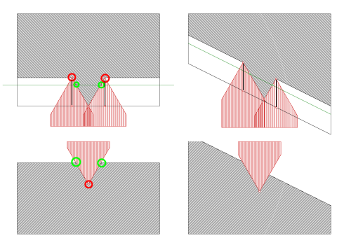 We experimented a bit, and found that this will only work for 3D surfaces with a very shallow curvature (gentle slopes), see the image above. Material (base and plug) in gray, V-bit cutter in red. The green points indicate the artwork curves. the red points are points on the toolpath. DeskProto calculates an XY position and a depth below the top surface. For a horizontal surface that works fine, however as you can see for a sloped surface the position of the top of the ridge (on the plug) does not match with the bottom of the groove. |
|
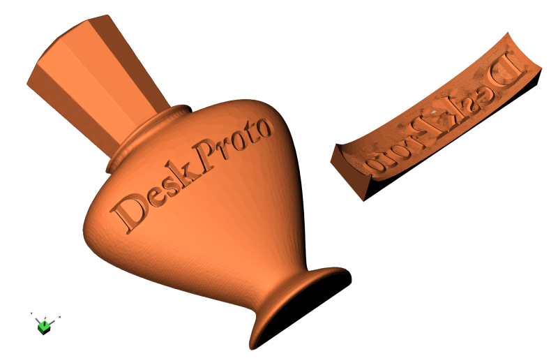
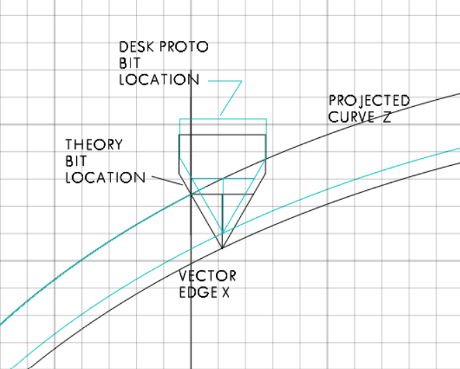 I was going to post this on a separate thread when I saw this one. Seeing there are others interested in this process. Inlay on curved surface Lex I have enjoyed doing some inlay projects, V8.0 makes it much easier than other affordable software I experimented with. I had a crazy thought, can an inlay be done on a curved surface. Was pleasantly surprised when I could project a vector curve onto a 3D geometry ( 160 x 80 ellipse) and do a V-carve Vector operation like a normal V-carve Inlay. Was able to cut the inlay on the 3D geometry 4mm depth and the plug with a -3 mm curve depth. When trying to insert the plug into the inlay the plug was too big , mostly in the X direction. In trying to figure out the problem I made a test part. Vector 100 mm X 10 mm Y projected on the same curve geometry. Using this it clearly showed the plug was indeed too long in the X, about 1.5 mm. To further the investigation I drew it out in CAD using what should happen in theory and tool locations from the Desk Proto G-code file. This shows that the tool X position follows the vector at the V width at the cut depth. ( which it should). But the Z depth follows the curve at tool center line. So as the vector curves down the intersection of cut and Vector Z is not at vector X (-0.7 mm). Hope this makes some sense. Don't know how difficult it would be to calculate the Z depth based on V tool width at depth of cut. Or if this type of inlay would be of interest to other DP users. Was able to do a successful simple inlay by scaling the X and Y movement (.986) in the post processor for the plug, making it 1.4 mm smaller . It worked for this particular inlay but the error correction would have to be figured out for every curve and or inlay size. |
|
 Inlay on curved surface vase from above post |
|
Hi DSP, My compliments about finding a workaround for this problem - unfortunately only valid for this one project. The issue is difficult to explain: I have problems understanding your image, just as you will have for my image. Still the explanation is the same: the position of the V-bit is calculated for a flat surface. When using that same position (in this case the X-value and the depth) on a sloped surface the design curve (so the curve that finally should be visible as division between the two wood types) will have an incorrect X-position. We do not yet have a solution to fix this. Adding a scaling factor is a good idea, however this will only work for cylindrical curved surfaces. Still thinking if we can find a better solution. Lex. |
|
Interesting |
|
|
|
|
|